FAQ –
Frequently asked questions.
How do I create a heat with more drivers than I have lanes. (Round-robin)
How can the best qualified driver be the first to choose lane.
When track power goes off, I sometimes get communication problems or
“unexpected reset”.
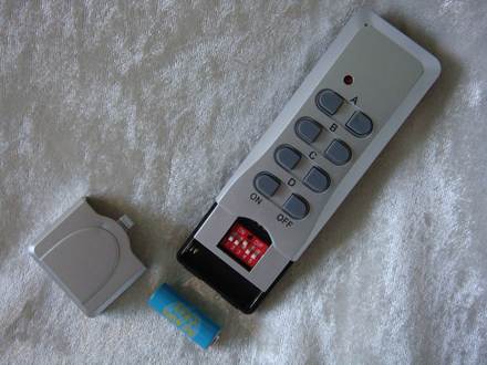
My remote control is not working.
LapMaster gets a different COM-port each
time I reconnect it to my computer.
Does LapMaster have a log of all laps
raced on the track.
How do I connect the LapMaster system.
How do I connect the LapMaster system to a
SRT power relay board.


|
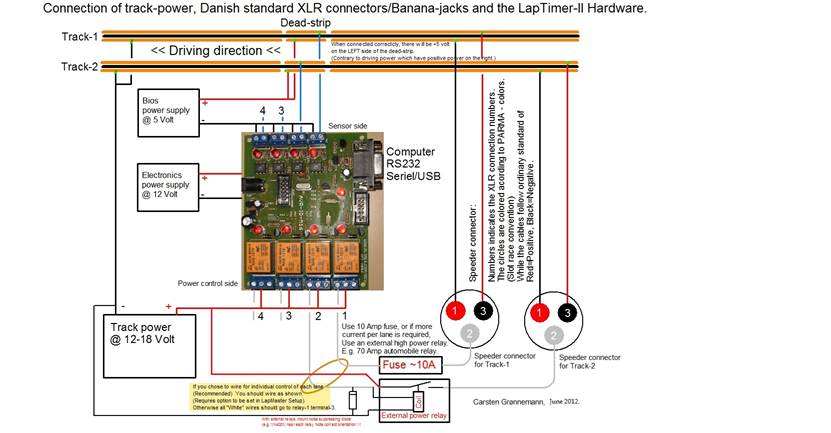
Question: How do I connect the
LapMaster system. Answer: You
might also have a look at this diagram: If
you are confused by the diagram, here is a more practical verbal guide on how
to connect a LapMaster system. Domestic Power: Deadstrip: These has been labeled Lane
1-4 and 5-8. Track power: If
you already have a SRT power relay connection board, see this How
do I connect the LapMaster system to a SRT power
relay board. It is
absolutely mandatory that your relay coils are equipped with what is known as
backlash-diodes. See
also: When track power goes off, I sometimes get communication
problems or “unexpected reset” Computer:
If
your Computer dosn't have
a serial port, use the supplied USB-to-Serial converter cable. When you
attach the cable the first time, the Computer If
you need to lengthen the distance from the computer to the LapMaster box, extend the serial cable. You should not
extend the USB cable. Software: After
installation, you must associate the LapMaster program
with the LapMaster hardware. To
do that, start the LapMaster program. Accept the
"Demo" mode the first time you start LapMaster. (LapMaster must be connected and powered). Click
"OK" to save the connection. LapMaster
will close. Start
LapMaster the second time. Now click on
"Setup"->"Track Setup", and customize LapMaster to suit your track. (Number
of lanes, lane colors, length, name etc.) Click on "OK" to
complete. LapMaster will close. You
can now restart LapMaster for the 3'rd time, and
you are now ready to race. LiveTiming: |
|
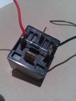
Question: How do I
connect the LapMaster system to a SRT power relay board. Answer: If
you have an existing SRT relay board hooked up, connection of LapMaster could not be any easier. The SRT
relay board looks like this: This is a
closeup of the relevant connections: The LapMaster box comes with relay connections wired to a screw
terminal connector block: That’s it,
for the power connection. See How do I
connect the LapMaster system. For the remaining
aspects. |


